

Encoder are the predefined digital blocks, these take some input and convert them into another form/format. For example BCD encoder.
BCD encoder has 10 inputs and ideally only one input should be high at a time, and this encoder will give out which input is high in 4 bit BCD output format. For example, when pin '2' is set to '1' and all other input to '0', the output will be "0010". This shows that the output gives count of the pin which is selected. Again if pin 5 is set to '1' and others to '0' then its BCD output will be "0101". A block diagram of such a encoder is shown below...
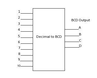
But in case more than one pin is set to '1', then the pin which has higher number will get the priority. For example suppose pin 3 and pin 7 both are set to '1', then input 7 will be taken and BCD output will be "0111".
Lets take a practical example and see where this encoder can be used. Suppose there are 9 devices, and each of them needs their data to get processed by a small microprocessor. In such scenario, we can connect these devices to the processor through Decimal-to-BCD encoder. Here we have the flexibility to connect the most important device to pin 9, and least important device to pin 1. Making connection like this gives them priority over one another.
Now, whenever devices are ready with data, each device will set data available to '1' which is connected to the input of decimal-to-bcd. On the output, BCD value of the highest priority requested device will be there. Once the processor process it, the device will de-assert its request and the processor can look at lower priority devices since BCD of lower priority device will be on the output now. In this way the processor will be able to serve each device depending on their priorities...
| Inputs | Outputs | |||||||||||||||||||||||||||||||||||||||||||||||||||||||||||||||||||||||||||||||||||||||||||||||||||||||||||||||||||||||||||||||||||||||||||||||
|
|
Below is shown truth table of BCD encoder which very much explains how
the encoder will behave for each input.