


Comparator can be designed to compare multi bit numbers. The figure below shows 2-bit comparator's block diagram
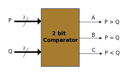
The comparator compares two unsigned number P and Q, and gives comparison result on three output pins A, B and C. Pin A goes high, if P is greater than Q; pin B goes high, if input P is equal to Q and pin C goes high, if the input P is less than Q.
Below is the truth table for comparator...
| Inputs | Outputs | |||||||||||||||||||||||||||||||||||||||||||||||||||||||||||||||||||||||||||||||||||||||||||||||||||||||||||||||||||||||
|
|
This circuit can be easily implemented using Karnaugh map, but for any
application, We suggest you to explore availability of any comparator IC
first.