


-
Resistor
- R1, R2 (470 ohms, 1/2W)
-
Transistor
- T1, T2 (AC128 or AC188)
-
Lamps
- L1 (6V, 60 mA)
- L2 (6V, 60 mA)
-
Miscellaneous
- S1 Push-to-on switch (single pole)
- S2 Push-to-on switch (single pole)
- S3 Toggle switch
- Battery 6V or 1.5 x 4 cells
- PCB or Breadboard
- Flexible Wire
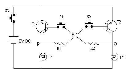
This is a very interesting and simple circuit. This also can be used in quiz events, where two participants hit their button to answer. The participant, who pressed his button first, will get a chance to answer first. This circuit will resolve which participant hit the button first, by glowing the lamps associated with the button.
When S3 is in ON position, base circuits of both the transistors remains
open and thus no current flows in their respective collector-emitter
circuits. Hence, both the lamps remain off.
Now, let S1 be pressed first, the transistor TR1 gets negative base
voltage through R1. Due to this transistor TR1 starts conduction, and
lamp L1 begins to glow. On account of this action the voltage at point P
drops to nearly zero value and if the push-button S2 is pressed in this
condition , the transistor TR2 gets no base voltage and it will remain
non-conduction.
Similarly when S1 is pressed first, the lamp(L2) associated with S1 will glow preventing L1 to glow. Since, at a time only one lamp will glow, this circuit will always give correct judgment.