


-
Resistor
- R1 (330 ohms, 1/2W)
- R2 (8.2K, 1/2W)
-
Capacitor
- C1 (500 uf, 16V)
- C2 (0.01 uf, 50V)
-
Transistor
- T1 (BC148B)
- T2 (AC128)
-
Diode
- D1 (BY125)
-
Transformer
- TR1 (230V to 6v step down, 200mA )
-
Miscellaneous
- Speaker (8 ohms)
- Neon lamp
- Pushbutton (S1)
- PCB or Breadboard
- Flexible wires
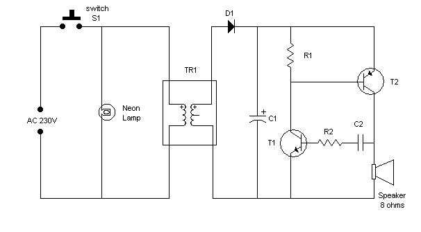
This is a very simple musical electronic bell. In this circuit when the push-button(S1) is pushed, current starts flowing through the transformer. This transformer is a step-down transformer which converts 230V AC to 16V AC. The stepped down voltage is passed through diode D1. Diode D1 behaves as a half wave rectifier and passes only positive voltage. This positive voltage is used to charge capacitor C1. The Charged capacitor C1 acts as a power source for low frequency oscillator. Transistor T1 and T2 are connected in such a way that they constitute a low frequency oscillator of 1 kHz. This oscillating voltage generates oscillating current which flows through the speaker, and generates a sweet tone. The pitch of the generated tone can be changed by using different values of R2 or by using preset of 10K ohms in place of R2.