


-
Resistor
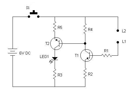
- R1 (68K , 1/2W)
- R2 (330K , 1/2W)
- R3 (1K, 1/2W)
- R4 (680 ohms, 1/2W)
- R5 (22 ohms, 1/2W)
-
Transistor
- T1 (BC107)
- T2 (AC128 or AC188)
-
LED
- LED1
-
Miscellaneous
- Battery, Dry cell 6V
- (L1, L2) Testing probes or crocodile clips
- S1 ( Slide switch, single pole)
- PCB or Breadboard
- Flexible Wire
This is a very simple and useful circuit which can be used for testing some electronic components. Like multimeter one can use this circuit for :- continuity testing, resistor testing, capacitor testing and diode testing.
In this circuit LED glows only when probes L1 and L2 are short-circuited or has a path for the current to flow. This fact will be used to test components.
Continuity Testing : Connect the two probes to the points between which the continuity has to be tested. If the LED glows! the points are electrically continuous otherwise not.
Resistor Testing : This circuit can test upto 10K resistors. If LED glows, resistor is good otherwise faulty.
Capacitor Testing : When a electrolytic capacitors is put in between L1 and L2 the LED should show glow momentarily. If the LED glows continuous, the capacitor is defective.
Diode Testing : A good diode will produce a glow in one direction only. If a diode produced glow in both directions, or in none of the direction, diode is faulty.
Transformer coil Testing : A good transformer winding should glow LED, but in case of "open circuited" faulty coil, the LED won't glow.