


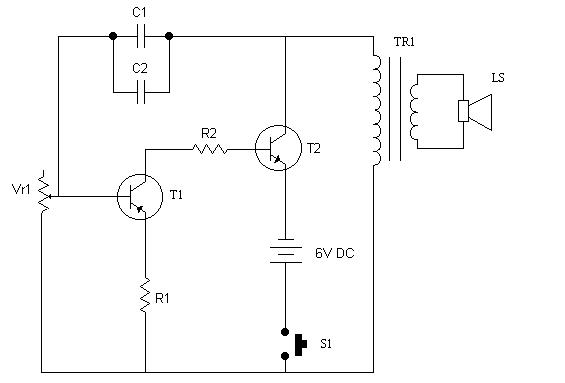
Circuit Diagram
Components Required
-
Resistors
- R1 (100 ohms , 1/2W)
- R2 (470 ohms , 1/2W)
-
Transistors
- T1 (AC126)
- T2 (LS100)
-
Capacitors
- C1 (0.22 uf, 50V)
- C2 (0.22 uf, 50V)
-
Preset
- Vr1 (2 Mega ohms)
-
Miscellaneous
- Battery 6V or Dry cell (6 x 1.5)
- LS ( Loudspeaker, 8 ohms, 6 cm diameter)
- S1 ( Slide switch, single pole)
- TR1 (Transformer)
- PCB or Breadboard
- Flexible Wire
Principle and Working
This is a very simple electronic bell. Here the transistor TR-1 acts as a low frequency oscillator. Transistor TR1 also acts as a pre-amplifier. Oscillations generated from TR-1 is fed to the transistor TR2 which is a small audio amplifier. Preset Vr1 can be used to vary frequency, which will change the output tone of the bell.