


A transistor is a three pin semiconductor component. Transistor is one or the most fascinating device which has not only revolutionized the whole electronics industry but also given birth to modern day computers and mobile devices. Essence of this device in its name itself, the word "semiconductor", which means it is not always conductor nor always insulator, its can change its property from conductor to insulator and vice-versa. This control to make it conductor or insulator is key function which makes this device so unique. Understanding transistor's working will open new door of creative use case and circuit implementation.
Transistors are generally of two types, NPN or PNP, understanding functionality of any one is sufficient.
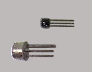
These three pin of the transistor are called emitter, collector and base as shown below.
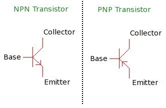
1) Transistor are of two types, PNP and NPN
2) In this article we will use NPN to understand its core principle.
3) Transistor can be considered same as a valve which is used to control flow of water between two connecting pipes, and the hand wheel is use to controls flow of water. In transistor we don't have hand wheel to control flow of current but there is some other way to control.
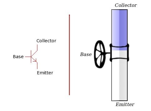
Lets understand working of transistor through an analogical model. The
image above shows a pipe carrying water and a valve controlling its
flow. Water entering from a section marked as collector . Flow of
water is getting controlled by valve named Base, and it is
coming out from a section marked emitter .
Now lets focus on some of the facts of this model.
- Small amount of force is required to turn the wheel which is controlling a large amount of water, and large amount of water force.
-
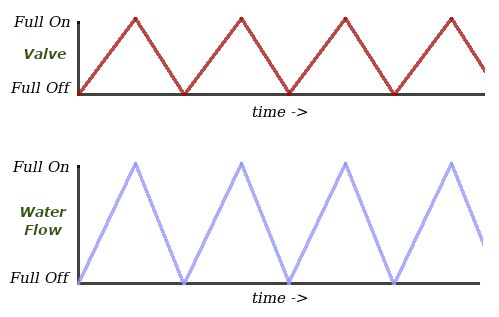
Any pattern that is followed for turning the wheel will be observed in
the water pattern of water coming out.
Lets understand this point clearly. Suppose some one changing the wheel in such a way that he is following a pattern with time, means he is turning valve slowly on, takes it to maximum on, then turns the valve slowly off and takes it to completely off. With this the outgoing water through valve will also follow the same pattern. This is shown in the image below.
Transistors also work in quite similar fashion. Large current which flows between collector and emitter is controlled through base pin (or base current). On transistors you won't find any flow control wheel, but a very small current fed at base pin controls the large emitter current. The emitter current will be always in in ratio of base current, and this ratio is constant for each transistor.This constant value is provided by manufacturer in data-sheet and is know as beta of the transistor. Betas are generally in range from 50 to 200. Which means, 1 unit of base current can control 200 units (for beta = 200) of emitter current. This is how in transistor small current is used to control large current. And also this is how transistor is used as amplifier, where a small base signal gets amplified. Small base signal current/pattern gets amplified to get large emitter current/pattern.
Hence, emitter_current = (base_current * Beta)
In Digital application, the same transistor is used as switch. As a switch can be either on or off, similarly a transistor also can be turned on (1) or off (0). When base current is 0, the transistor is off and no emitter current flows in response (like valve completely closed). When base current is sufficiently heigh that full emitter current is flowing (no blockage or resistance from valve, like valve completely open), the transistor is said to be on.
The arrow mark on transistor symbol shows the type of transistor (NPN or PNP), and also shows the direction of the current. e.g In npn transistor current flows from collector to emitter, whereas in PNP current flows from emitter to collector. In PNP transistor emitter current is controlled by drawing base current (not by feeding).